1. Overview
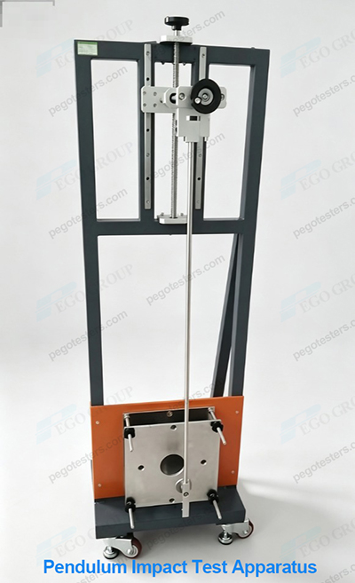
The pendulum impact test apparatus specified in Annex A of IEC 60309 1 Plugs, fixed or portable socket-outlets and appliance inlets for industrial purposes — Part 1: General requirements is special test equipment for verifying the mechanical strength of industrial socket-outlets and appliance inlet enclosures. It corresponds to the impact test in Clause 24.2 of the standard. Its nationally identical converted standard is GB/T 11918.1. The complete set of apparatus is fully defined by seven engineering drawings, Figure A.1 to A.7, covering structure, dimensions, materials and assembly relations. It is core equipment for type tests, factory quality inspection and capability verification of CNAS-accredited laboratories. It simulates rough handling, tool drop and collision in industrial sites to assess whether the insulation, protection and electrical performance of products fail after impact.
Test principle: The pendulum is released from a preset angle by gravity; gravitational potential energy is converted into impact kinetic energy. Impact energy is classified into four levels: 1 J, 2 J, 3 J and 4 J. Energy switching is realized by replacing pendulum weights. The test sample is mounted on a rigid anvil. After testing, the sample shall not develop cracking, dielectric breakdown or IP protection failure that impairs safety.
2. Description of Each Drawing Figure A.1 ~ A.7
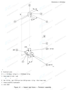
2.1 Figure A.1 Impact Test Apparatus — Pendulum Assembly
General assembly drawing of the complete equipment, showing the full pendulum assembly: pivot support, pendulum rod, stackable weights, impact head, release mechanism and rigid specimen base. This drawing defines the height of the swing centre, pendulum swing radius and locking/release structure. It ensures the pendulum swings freely with negligible extra friction, and the normal of the impact head is perpendicular to the specimen surface at the instant of impact. This drawing serves as the primary reference for equipment fabrication, overall assembly and acceptance calibration.
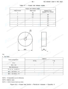
2.2 Figure A.2 Impact Test Apparatus — Pendulum Mass (Quantity: 4 pcs)
Four separate steel weights 0.25kg, the core components for graded impact energy. Different combinations of added/removed weights match 1 J to 4 J impact levels. The weights are machined carbon steel parts with tight dimensional tolerances and flat surfaces. They can be sleeved and fixed onto the pendulum shaft without slipping after locking. The mass of each weight is metrologically calibrated. The total mass after combination directly determines impact energy, making these weights key traceable components for equipment metrology.
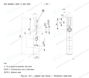
2.3 Figure A.3 Impact Test Apparatus — Pendulum Shaft End
Detail drawing of the end of the pendulum rod, defining the shaft profile, positioning shoulders and thread locking structure for mounting the impact head and weights. The shaft end design ensures concentric installation of weights, eliminates eccentric moment during impact and avoids lateral force that distorts impact energy.
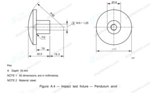
2.4 Figure A.4 Impact Test Apparatus — Pendulum Anvil (Specimen Base)
Rigid mounting anvil, made of heavy steel base firmly fixed to concrete or heavy test bench. No obvious displacement or elastic deformation shall occur during testing. Adjustable tooling on the anvil allows adjustment of specimen mounting angle and height, so the impact point can be accurately aligned with weak positions on the product enclosure (enclosure wall, cover, locking ring, etc.). Rigidity of the anvil is critical for test repeatability. Elastic rebound of the base will alter the actual impact energy.
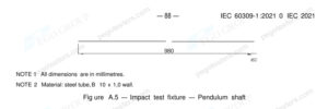
2.5 Figure A.5 Impact Test Apparatus — Pendulum Shaft (Pendulum Rod)
Hollow steel tube pendulum rod with diameter 10mm, 1.0mm thickness and 980mm length. The pendulum rod shall have sufficient bending stiffness with minimal elastic deformation during impact. Meanwhile, its self-weight is controlled to prevent extra deviation of impact energy introduced by the rod mass. The upper end connects to the swing pivot, and the lower end connects to the shaft end assembly.
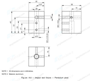
2.6 Figure A.6 Impact Test Apparatus — Pendulum Pivot
Detail drawing of the swing hinge structure, designed for low friction. Bearing resistance of the pivot shall be as small as possible to ensure negligible energy loss during pendulum downward swing. Coaxiality and clearance of the pivot directly affect the pendulum trajectory. Sticking or excessive clearance of the pivot will cause dispersion of impact energy and poor repeatability of test results. Periodic equipment calibration shall check pivot rotation performance.
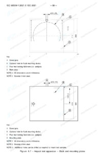
2.7 Figure A.7 Impact Test Apparatus — Back and mounting plates
The black plate and mounting plate are made of 8mm steel, used to install and fix the samples.
3. Key Technical Points of the Apparatus
3.1 Test Acceptance Criteria Minor cracks are permitted after impact. However, the sample shall not suffer: exposure of live parts, insulation damage, electric leakage, failure of protection structures or breakage compromising subsequent electrical safety. Withstand voltage and insulation resistance shall be rechecked after the test.
3.2 Equipment Maintenance & Calibration
– Periodically check whether the pivot (Figure A.6) rotates smoothly; clean bearings;
– Inspect pendulum rod, weights and impact head for deformation and dents;
– Verify tightness of anvil fixing;
4. Application Scenarios
4.1 Type tests of industrial plugs and socket-outlets in accordance with IEC 60309 1 / GB/T 11918.1 for mechanical strength;
4.2 R&D phase comparison of impact resistance of different enclosure materials (glass-fibre reinforced plastic, modified nylon);
4.3 Equipment acceptance for third-party testing laboratories and factory QC laboratories;
4.4 Witness testing for product certification (CE, CCC, etc.).
5. Conclusion
Figures A.1 to A.7 in Annex A of IEC 60309 1 form a complete and self-consistent engineering specification for the pendulum impact apparatus. Each drawing independently defines technical requirements, covering overall assembly, pendulum rod, weights, pivot, anvil and release mechanism. Distinct from the general spring hammer, this gravity pendulum delivers higher impact load and stable energy, specially designed for mechanical strength assessment of industrial electrical accessories. In the field of industrial electrical accessory safety, this apparatus serves as an important test means to guarantee reliable enclosure structure and intact electrical safety of products under harsh working conditions.