1. Scope and Application of IEC62262
The IEC62262 standard describes a system for classifying the degrees of protection provided by enclosures for electrical equipment against mechanical impacts when the rated voltage of the protected equipment is not greater than 72.5KV. In general, the degree of protection applies to the complete enclosure. If parts of the enclosure have differing degrees of protection, the latter shall be indicated separately.
2. Object of IEC62262
- The definitions for the degrees of protection provided by enclosures of electrical equipment as regards protection of the equipment inside the enclosure against harmful effects of mechanical impacts;
- The designations for the degrees of protection;
- The requirements for each designation;
- The tests to be performed to verify that the enclosure meets the requirements of IEC62262.
3. What is IK Code?
It’s a code system to indicate the degree of protection provided by an enclosure against harmful external mechanical impacts. The characteristic group numeral of IK code is 00 to 10, it includes IK00, IK01, IK02, IK03, IK04, IK05, IK06, IK07, IK08, IK09 and IK10. Each characteristic group numeral represents an impact energy value as shown in below table 1.
Table 1 – Relation between IK Code and Impact Energy
IK code | IK00 | IK01 | IK02 | IK03 | IK04 | IK05 | IK06 | IK07 | IK08 | IK09 | IK10 |
Impact energy, J | * | 0.14 | 0.2 | 0.35 | 0.5 | 0.7 | 1 | 2 | 5 | 10 | 20 |
* Note: Not protested according to this standard | |||||||||||
Note 1 When higher impact energy is required, the value of 50J is recommended. Note 2 A characteristic group numeral of two figures has been chosen to avoid confusion with some national standards which used a single numeral for a specific impact energy. | |||||||||||
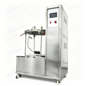
4. Test Apparatus of IEC62262
The test shall be done by using one of the test apparatus described in IEC60068-2-75. The relevant product specified in IEC60068-2-75 as follows:
IEC60068-2-75:2014 Clause and Figures | Corresponding to Pego’s testing equipment |
Clause 5 Test Eha: Pendulum hammer and Annex D | |
Clause 5.1.2 | |
Clause 5.1.3 | |
Clause 6 Test Ehb: Spring hammer and Annex E | |
Clause 7 Test Ehc: Vertical hammer | |
Annex A Shapes of striking elements | |
Annex B Procedure for the Calibration of spring hammers | |
Figures: |
|
Figure 1 | |
Figure A.1, A.2, A.3, A.4, A.5 and A.6 | |
Figure B.1, B.2, B.3, B.4 | |
Figure B.5, B.6 | |
Figure D.1, D.2, D.3, D.4, D.5 | |
Figure E.1 | |