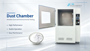
1. What is the Draught-Free Enclosure?
Draught-proof enclosure is designed according to IEC60598.1 annex D, it is applied to thermal test of luminaire under the conditions of normal operation and abnormal operation. The draught-proof enclosure is rectangular, with a double skin on top and on at least three side, and with a solid base. The double skins are of perforated metal, spaced approximately 150mm apart, with regular perforations of 1mm to 2mm diameter, occupying about 40% of the whole area of each skin. At the top of enclosure shall mounted a ceiling plate or a dismountable hanging bracket with a hook to fix the luminaire at the ceiling. At the bottom of side of enclosure shall install inlet hole for the purpose of wire connection. For the sake of install luminaire, the enclosure equip with a sample holder, as per the standard, 2-layer black solid-board is applied to fix the luminaire under test.
2. How to Interpret the Parameters of Draught-Free Enclosure?
| Technical type | Specific parameters | Explanation |
| Normative standard | IEC60598-1 (GB7000.1) Annex D | Complies with international and GB general standards for lamp testing, ensuring test results are compliant and valid |
| Overall structure | Rectangular structure with double shell on top + 2 sides and a solid base | Double-layer design controls airflow, and a solid bottom ensures structural stability |
| Shell material and process | Cold sheet metal punching + matte black paint spraying, thickness about 1mm | Taking into account ventilation and rust and corrosion resistance, the matte coating reduces light reflection |
| Ventilation design | The double-layer shell is 150mm apart, the hole diameter is 1-2mm, and the opening area accounts for 40% | Avoid air convection interference and accurately control the airflow in the test environment |
| Internal dimensions | Basic internal dimensions ≥ 900mm (three dimensions) | Can accommodate various common lamps for testing |
| Clearance requirements | 1. The distance between the inner surface and the largest lamp is ≥ 200mm. 2. The clearance above the top/around the perforated side is ≥ 300mm. |
Prevent space constraints or external factors from affecting test accuracy |
| Detailed design | 1. Multiple side cable entry holes 2. Single door per floor, staggered door gaps 3. Heavy steel structure frame on top |
The wire entry hole facilitates wiring, the door gaps are staggered to avoid ventilation interference, and the frame ensures load-bearing and stability |
| Stencil Process | High-quality steel plate + CNC punching, welding and assembly, then powder coating and baking paint | Ensure the mesh aperture and spacing are accurate, and the overall structure is stable and durable |