IEC 60598-1 standard is a standard formulated by the International Electrotechnical Commission (IEC) for evaluating the safety performance of luminaires. It mainly specifies the general safety requirements for luminaires. This standard covers aspects such as electrical safety, mechanical safety, and protection, ensuring that luminaires will not cause hazards such as electric shock and overheating under normal use, thus protecting the personal safety of users.
This article summarizes the testing equipment corresponding to the relevant clauses, and proposal the test solution of standard IEC60598-1 : 2020. Details as below table:
| IEC60598-1:2020 Clauses and figures | Corresponding testing equipment from Pego |
| Section 4 Construction | |
| 4.4.4 Lamp holder installation requirements–Mechanical tests | Double ended “go” gauges for a combined pair of lampholders G5 (7006-47C) Double ended “go” gauges for a combined pair of lampholders G13 (7006-60C) Lampholders Axial Force Test Device |
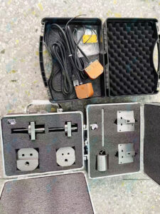
| 4.7 Terminals and supply connections | standard test finger |
| 4.10 Double and reinforced insulation | test probe 13 (clause 4.10.2) IP code test probe kits (clause 4.10.2) 1nF impulse voltage generator (clause 4.10.4) |
| 4.11 electrical connections and current carrying parts | Electro-mechanical contact system testing device (clause 4.11.6, figure 31) |
| 4.12 screws and connections (mechanical) and glands | Digital lampholder torque Meter (clause 4.12.4) Screwed Glands Torque Test Apparatus (clause 4.12.5) |
| 4.13 mechanical strength | Spring-operated impact test apparatus (clause 4.13.1) IEC straight unjointed test finger with 30N thruster (clause 4.13.3) 50mm steel ball (clause 4.13.4 a), figure 21) Inclined plane (clause 4.13.4 c)) IEC60068-2-31 tumbling barrel (clause 4.13.6) |
| 4.14 Suspensions, fixings and means of adjustment | Suspended luminaire torque test device (test B) Rigid Suspension Brackets Test Device (test C) |
| 4.18 resistance to correction | Heating cabinet |
| 4.20 rough service luminaires-vibration requirements | Vibrator |
| 4.26 short-circuit protection | Luminaire test chain (clause 4.26.3 / figure 29) |
| 4.35 protection against moving fan blades | standard test finger with 30N thruster test probe 19 |
| Section 5: external and internal wiring | |
| 5.2 supply connection and other external wiring | Cord anchorage pull force and torque tester (clause 5.2.10.3) |
| Section 8: protection against electric shock | |
| 8.2 protection against electric shock | standard test finger, 50mm test sphere (clause 8.2.1) electrical indicator (clause 8.2.5) |
| Section 9: resistance to dust, solid objects and moisture | |
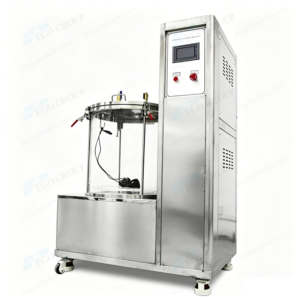
| 9.2 tests for ingress of dust, solid objects and moisture | IPX1/2 drip box (clause 9.2.3) IPX3/4 oscillating tube (clause 9.2.4 & clause 9.2.5 / figure 7) IPX5/6 jet nozzles (clause 9.2.6 & clause 9.2.7/ figure 8) IPX7 water tank (clause 9.2.8 IPX8 high pressure water tank (clause 9.2.9) IPX9 high pressure and temperature fan spray test chamber (clause 9.2.10 & clause 9.2.11) IP5/6X dust chamber (clause 9.2.1 / figure 6) IP code test probes kits (clause 9.2.0) |
| 9.3 Humidity test | temperature and humidity test chamber |
| Section 10: insulation resistance and electric strength, touch current and protective conductor current | |
| Clause 10.2 insulation resistance and electric strength | insulation resistance tester (clause 10.2.1) withstand voltage tester (clause 12.2.2) |
| Section 11: creepage distances and clearances | |
| 11.2 Creepage distances and clearances | Standard test finger (clause 11.2.1) Creepage distance caliper (clause 11.2.2) |
| Section 13: resistance to heat, fire and tracking | |
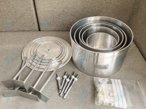
| 13.2 resistance to heat | ball pressure test apparatus, heating cabinet (clausse 13.2.1 / figure 10) |
| 13.3 resistance to flame and ignition | needle flame tester (clause 13.3.1) glow-wire tester (clause 13.3.2) |
| 13.4 resistance to tracking | tracking index tester (figure 11) |
| Annex A Test to establish whether a conductive part can cause an electric shock | 50KΩ non-inductive resistor (clause A.2) |
| Annex D Thermal testing | draught-proof enclosure multiplex temperature recorder |
| Figures | |
| Figure 6-apparatus for proving protection against dust | dust chamber |
| Figure 7- apparatus for testing protection against rain and splashing | oscillating tube test equipment |
| Figure 8 – nozzle for spray test | jet nozzle testing equipment |
| Figure 10 – ball pressure apparatus | ball pressure test apparatus |
| Figure 11 – arrangement and dimensions of electrodes for tracking test | tracking index tester |
| Figure 21 – apparatus for ball impact tests | ball impact test apparatus |
| Figure 29 – test chain | short-circuit test chain |
| Figure 31 – electro-mechanical contact system with plug / socket connection | Electro-mechanical contact system testing device |