IEC60068-2-75 Environmental testing: Hammer Tests
1. Introduction of IEC60068-2-75
The IEC60068-2-75 standards provides three standardized and coordinated test methods for determining the ability of a specimen to withstand specified severities of impact. It is used, in particular, to demonstrate an acceptable level of robustness when assessing the safety of a product and is primarily intended for the testing of electrotechnical items. It consists of the application to the specimen of a prescribed number of impacts defined by their impact energy and applied in the prescribed directions. The IEC60068-2-75 covers energy levels ranging from 0.14J to 50J.
2. Interpretation of the Core Content of the Standard
2.1 Purpose of the hammer impact test:
Now, let’s delve into the core content of this standard. The purpose of the hammer impact test is to simulate the accidental impacts that products may suffer during actual use, such as product drops or impacts from external objects. Through this test, we can evaluate the structural integrity of the product, the stability of internal components, and whether the product can continue to work normally after being impacted. This ensures that the product has sufficient resistance to physical impacts and guarantees the product’s safety after being put on the market.
2.2 Test methods of hammer impact test:
In addition, the standard provides three standardized and coordinated test methods. Each method has specific regulations regarding impact energy, impact direction, and the number of impacts.
2.3 Key test parameters of hammer impact test:
Moreover, there are some key test parameters.
2.3.1 For impact energy, the weight of the hammer and the free-fall height used in the hammer impact test are designed in a standardized way. The impact energy ranges from 0.14 joules (J) to 50 joules (J). Different product types and application scenarios correspond to different impact energy requirements. For instance, some small electronic devices may only need to withstand low-energy impacts, while large industrial equipment needs to deal with high-energy impacts.
2.3.2 When it comes to fixing the test sample, during the test, the sample must be firmly fixed on the bracket, and any displacement of the sample should be prevented during the test. This ensures the consistency of the impact point and the impact effect of each test, so as to obtain accurate and reliable test results.
2.3.3 Regarding the impact direction, in order to comprehensively evaluate the impact resistance of the product, the test is usually carried out in multiple directions, including horizontal, vertical, and diagonal directions. This is because the direction of the impact that the product may suffer in actual use is uncertain. Testing in multiple directions can more realistically simulate the actual situation.
2.4 Test process
The test process consists of three stages.
2.4.1 In the preparation stage, we need to ensure that the test sample is intact without any damage or defects that may affect the test results. Also, we should check and calibrate the test equipment to ensure that the equipment can accurately generate the specified impact energy and fix the test sample according to the standard requirements.
2.4.2 Then, in the execution stage, we should strictly apply the specified number of impacts, energy, and direction to the sample according to the selected test method. During this process, we need to accurately record relevant data of each impact, such as impact time and impact energy.
2.4.3 Finally, in the evaluation stage, after the impact test is completed, a comprehensive performance evaluation of the product is carried out. This includes electrical performance testing to check whether there are short circuits, open circuits in the product circuit, and whether the electronic components are damaged; mechanical strength inspection to check whether the product structure is deformed or cracked, and whether the components are loose; and appearance damage inspection to record scratches, dents, and other situations on the product surface. Based on the results of various evaluations, we can determine whether the product passes the test.
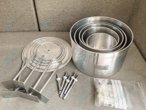
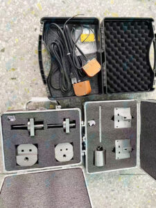
3. Pego’s corresponding testing equipment of IEC60068-2-75 as below table:
|
IEC60068-2-75:2014 clause and figures |
Corresponding to Pego’s testing equipment |
|
Clause 5 Test Eha: Pendulum hammer and Annex D |
IK01-06 Pendulum Hammer Impact Testing Machine (Clause 5.1.2 and Figure D.1, D.2, D.3, D.4, D.5) IK07-11 Pendulum Hammer Impact Testing Machine (Clause 5.1.3) |
|
Clause 6 Test Ehb: Spring hammer and Annex E |
|
|
Clause 7 Test Ehc: Vertical hammer |
|
|
Annex A Shapes of striking elements |
IK06 Striking Element (Figure A.1) IK07 Striking Element (Figure A.2) IK08 Striking Element (Figure A.3) IK09 Striking Element (Figure A.4) IK10 Striking Element (Figure A.5) IK11 Striking Element (Figure A.6) |
|
Annex B Procedure for the Calibration of spring hammers |
Spring Hammers Calibration Device (Figure B.1, B.2, B.3, B.4) Spring Hammer Calibration Device Calibrator (Figure B.5, B.6) |