BS 1363 is a series of British standards for electrical plug and socket systems. Among them, BS 1363-1 specifically sets the specifications for 13A fused plugs, both rewirable and non-rewirable. This standard applies to 13A fused plugs with insulated phase and neutral pins, used in domestic, commercial, and light industrial settings where special safety considerations are required during normal use. These plugs are suitable for alternating current circuits with a frequency of 50Hz or 60Hz and a root-mean-square voltage not exceeding 250V, and can be used to connect devices, audio-video equipment, lighting fixtures, and more.
Application Scope of BS1363-1
BS 1363-1 encompasses a wide range of content. It begins with defining terms related to plugs, such as plug, rewirable plug, and non-rewirable plug. It then clearly states the general requirements for the design and construction of plugs, emphasizing that they must perform reliably under normal use and pose no danger to users or the surrounding environment. The standard also details the general conditions for type tests, requirements for test samples, and specifies that all tests are type tests. Additionally, it covers specific requirements and test methods for the performance of plugs, including resistance to aging, moisture, insulation resistance, electrical strength, resistance to abnormal heat, fire, and tracking. The importance and significance of BS 1363-1 are profound.
Importance and significance of BS1363-1
For manufacturers, compliance with this standard ensures that their produced plugs are compatible with sockets in the BS 1363 series, meet regulatory requirements, and satisfy relevant certification schemes, facilitating product acceptance in the UK and some overseas markets. For suppliers, retailers, and consumers, it guarantees that plugs manufactured in accordance with this standard are of good quality and can function correctly, safely, and reliably even after multiple insertions and removals.
The following table lists the test gauges and equipment required for BS 1363-1 testing.
| BS1363-1:2016 Clauses and figures | Corresponding Testing Equipment from Pego |
| Clause 8 Clearances, creepage distances and solid insulation | |
| 8.2 Creepage distance | Creepage distance caliper |
| 8.3 Solid insulation | Withstand voltage tester |
| Clause 9 accessibility of live parts | Test probe 12 (subclause 9.1.1) Apparatus for mechanical strength test on resilient covers (Subclause 9.3.1 & figure 2) Test probe 11 (Subclause 9.3.1) |
| Clasue 10 provision for earthing | Earth resistance tester |
| Clause 12 Construction of plugs | gauge for plug pins (figure 5 and clause 12.2) Dimensions and dispostion of pins (figure 4a and clause 12.2) Apparatus for testing plug cover fixing screws (figure 6 and clause 12.6) Heating cabinet (clause 12.6) Test pin (figure 1 and clause 12.2) Test probe 11 with 30N force (clause 12.7) Apparatus for tests on plug pins (figure 32 and clause 12.9) plug and socket-outlet life tester (subclause 12.9.5.1) Apparatus for torsion test on pins (figure 33 and subclause 12.9.6.1) Plug Pins Fixation Verifying Test Apparatus (Figure 7 and clause 12.11.1) Plug pin deflection test apparatus for resilient plugs (figure 8 and clause 12.12) Withstand voltage tester (subclause 12.17.2) Apparatus for abrasion test on insulating sleeves of plug pins (figure 9 and subclause 12.17.3) Apparatus for pressure test at high temperature (figure 10 and subclause 12.17.4) |
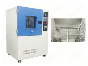
| Clause 14 Resistance to ageing and to humidity | Heating cabinet (clause 14.1) Tempeature and humidity test chamber (clause 14.2) |
| Clause 15 insulation resistnace and electric strength | Insulation resistance tester (subclause 15.1.2) Withstand voltage tester (subclause 15.1.3) |
| Clause 16 Temperature rise | Test apparatus for temperature rise test (clause 16.1.1) |
| Clause 17 Breaking capacity of swithes incorporated in fused plugs | Switch breacking capacity and normal operation testing machine Power load cabinet |
| Clause 18 Normal operation of switches | |
| Clause 19 Connection of flexible cables and cable anchorage | Flexing test apparatus (figure 18 and clauses 19.1 and 19.5.1) |
| Clause 20 Mechanical strength | Solid link for tset on fuse clips (figure 19 and clause 20.1.2) Tumbling barrel (figure 20 and clause 20.1.3) |
| 21 Screws, current-carrying parts and connections | Torque screwdriver (Subclause 21.1.1) |
| 22 Resistance to heat | Heating cabinet (clause 22.1.2) Heat Compression Test Apparatus (figure 23 and clause 22.1.3) |
| 23 Resistance to abnormal heat and fire | Glow wire tester (clause 23.2) |
| Figures | |
| Figure 1 – test pin | Test Pin |
| Figure 2a Apparatus for mechanical strength test on resilient covers | Apparatus for mechanical strenth test on resilient covers |
| Figure 2b – Hardwood block | |
| Figure 5 – gauge for plug pins | gauge for plug pins |
| Figure 6 – Apparatus for testing plug cover fixing screws | Apparatus for testing plug cover fixing screws |
| Figure 7 Mounting plate | Plug Pins Fixation Verifying Test Apparatus |
| Figure 8 – Plug pin deflection test apparatus for resilient plugs | Plug pin deflection test apparatus for resilient plugs |
| Figure 9 Apparatus for abrasion test on insulating sleeves of plug pins | Apparatus for abrasion test on insulating sleeves of plug pins |
| Figure 10 – Apparatus for pressure test at high temperature | High temperature pressure test apparatus |
| Figure 11 – go gauge for socket-outlet | Go gauge for socket-outlet |
| Figure 17 – test apparatus for temperature rise test | Temperature rise test apparatus |
| Figure 17b – dummy front plate for temperature rise | |
| Figure 18 – apparatus for flexing test | Flexing test apparatus |
| Figure 19 – Solid link for test on fuse clips | Solid link for test on fuse clips |
| Figure 20 – Tumbling barrel | Tumbling barrel |
| Figure 23 Apparatus for pressure test | Heat Compression Test Apparatus |
| Figure 32a – Apparatus for tests on plug pins | Apparatus for tests on plug pins |
| Figure 33 – Apparatus for torsion test on pins | Apparatus for torsion test on pins |
| Annex A The construction and calibration of a calibrated link | Calibrated link (figure 28) Calibration jig for calibrated link (figure 29) |
| Annex B Measurement of clearances and creepage disances | Creepage distance caliper |
| Annex C Determination of the comparative tracking index (CTI) and Proof tracking Index (PTI) | Tracking index tester |
| Annex F Impulse voltage test | 1.2/50μs Impulse voltage generator |