1. Scope:
The standard IEC60669-1 applies to manually operated general purpose switches, for a.c. only with a rated voltage not exceeding 440V and a rated current not exceeding 63A, intended for household and similar fixed electrical installations, either indoors or outdoors.
2. Switches Can Be Tested
– A circuit for a tungsten filament lamp load;
– A circuit for a fluorescent lamp load (including electronic ballast);
– A circuit for a substantially resistive load with a rated current up to 10A and a power factor not less than 0.6;
– A combination of these.
– Switches incorporating pilot lights;
– Electromagnetic remote control switches;
– Switches incorporating a time-delay device;
– Combinations of switches and other functions;
– Switches having facilities for the outlet and retention of flexible cables
– Isolating Switches.
3. List of IEC60669-1 Equipments
Pego supplies the corresponding testing equipment of IEC60335-1 as below table:
IEC60669-1: 2017 Clause and Figures | Corresponding to Pego’s Testing Equipment |
Clause 7 Classification | |
Clause7.1.4 | |
Clause7.1.9 | |
Clause 10 Protection against electric shock | |
Clause 10.1 | |
Clause 12 Terminals | |
Clause 12.2.5 figure 10 and Table 4 Clause 12.3.10 | |
Clause 12.2.6 Table 5 | Pulling Out Test Apparatus |
Clause 12.2.8 | |
Clause 12.3.12 Figure 11 and Table 10 | |
Clause 13 Constructional requirements | |
Clause 13.15.1 and 13.15.2 | |
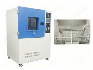
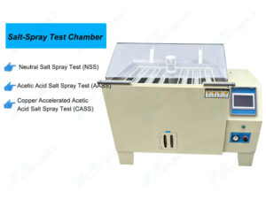
Clause 15 Resistance to Ageing, protection provided by enclosure of switches, and resistance to humidity | |
Clause 15.2.2 Figure 27 | Test Wall |
Clause 16 Insulation resistance and electric strength | |
Clause 16.2 | |
Clause 17 Temperature rise | |
Clause 17.1 | Wooden block 500*500*20mm |
Clause 18 Making and breaking capacity Clause 19 Normal Operation | |
Clause 20 Mechanical strength | |
Clause 20.2 Pendulum hammer test | |
Clause 20.4 Screwed glands Table 22 | |
Clause 20.5.2 Verification of the non-removal of covers, cover plates or actuating members (Figure 13) | |
Clause 20.8 Covers, cover plates or actuating members – application of gauges (Figure 14) | Gauge for The Verification of The Outline of Covers, Cover-Plates or Actuating Members |
Clause 20.9 Grooves, holes and reverse tapers (Figure 17) | Gauge for Verification of Grooves, Holes and Reverse Tapers |
Clause 21 Resistance to heat | |
Clause 21.2 Basic heating test | |
Clause 21.3 Ball-pressure test on parts of insulating material necessary to retain current – carrying parts and parts of the earthing circuit in position | |
Clause 21.4 Ball-pressure test on parts of insulating material not necessary to retain current-carrying parts and parts of the earthing circuit in position | |
Clause 22 Screws, current-carrying parts and connections | |
Clause 22.1 General | |
Clause 23 Creepage distance, clearances and distances through sealing compund | |
Clause 23.1 General Table 23 | |
Clause 24 Resistance of insulating material to abnormal heat, to fire and to tracking | |
Clause 24.1 Resistance to abnormal heat and to fire | |
Clause 24.2 Resistance to tracking | |