| BS1363-2:2016 + A1: 2018 Clauses and figures | Corresponding Testing Equipment from Pego |
| Clause 3 Terms and Definitions |
| 3.26 accessible external surface of a socket-outlet | Test probe B |
| 3.37 Engagement surface of a socket-outlet | Go gauge for socket (figure 11) |
| Clause 5 General conditions for type testing |
| 5.3 Dimensional verification | Go gauge for socket-outlet (figure 11)
Contact test gauge (figure 12)
Non contact test gauge (figure 14)
Withdrawal pull gauges for effectiveness of contact (figure 16a, figure 16b) |
| Clause 8 Clearances, creepage distance and solid insulation |
| 8.2 creepage distances | Creepage distance caliper |
| 8.3 Solid insulation | withstand voltage tester |
| Clause 9 Accessibility of live parts | Test pin ( subclause 9.1.1 & figure 1)
Apparatus for mechanical strength test on resilient covers (subclause 9.3.1 & figure 2a)
Test Probe 11 (subclause 9.3.1)
Rigid metal pin (φ1mm-60mm length, with 5N force) (subclause 9.4.1) |
| Clause 10 provisions for earthing | Torque Screwdriver (Table 6) |
| Clause 13 Construction of socket-outlets | Go gauge for socket-outlet (Subclause 13.1.1 & figure 11)
Contact test gauge (Subclause 13.2.1 & figure 12)
Non contact test gauge (Subclause 13.3.1 & figure 14)
Withdrawal pull gauges for effectiveness of contact (Subclause 13.4.1 & figure 16a, figure 16b)
Turning moment gauge (Subclauses 13.5.1 and 13.6.1 & Figure 15)
Test pin (Subclauses 13.7.1 and 13.13.1 & figure 1)
Test probe B (Subclause 13.13.1)
Test probe 11 (Subclause 13.19.1) |
| Clause 14 Resistance to ageing, resistance to humidity and protection provided by enclosures | |
| 14.1 Resistance to ageing | Heating cabinet |
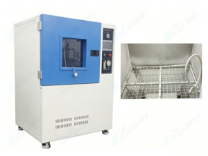
| 14.2 Resistance to humidity | Temperature and humidity test chamber |
| 14.3 Protection provided by enclosures | IP5X and IP6X Dust chamber (Subclause 14.3.2.1)
IP1X to IP4X code test probes
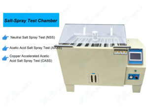
IPX1 to IPX9 waterproof test equipment |
| Clause 15 Insulation resistance and electric strength | Insulation resistance tester
Withstand voltage tester |
| Clause 16 Temperature rise | Test plug for temperature rise (Figure 30 &annex G)
Caliration jig for calibrated link (Figure 29 & annex A) |
| Clause 17 Breaking capacity of socket-outlets | Switch plug and Socket-outlet life tester
Power load cabinet |
| Clause 18 Normal operation of socket-outlets |
| Clause 19 Connection of flexible cables and cable anchorage | Cord anchorage pull force and torque tester (Subclause 19.1.1)
Test probe B (Subclause 19.2)
Power cord flexing test apparatus ((Subclause 19.5.1 & figure 18) |
| Clause 20 Mechanical strength | Solid link for test on fuse clips (Subclause 20.1.2 and figure 19)
Pendulum impact test apparatus (Subclause 20.1.3 and figure 21)
Tumbling barrel (Subclause 20.1.4 and figure 20) |
| Clause 22 Resistance to heat | Heating cabinet (Subclause 22.1.2)
Test probe 11 (Subclause 22.1.2)
Heat compression test Apparatus (Subclause 22.1.3 & figure 23)
Ball pressure test apparatus (Subclause 22.2.1) |
| Clause 23 Resistance to abnormal heat and fire | Glow wire tester (clause 23.2) |
| Clause 26 Cyclic loading test | Test plug for temperature rise (Figure 30 &annex G)
Go gauge for socket-outlet (figure 11) |
| Figures |
| Figure 1 -Test pin | Test Pin |
| Figure 2 (a, b) – Apparatus for mechanical strength test on resilient covers | Apparatus for mechanical strength test on resilient covers |
| Figure 11 – Go gauge for socket-outlet | Go gauge for socket-outlet |
| Figure 12 – Contact test gauge | Contact test gauge |
| Figure 14 – Non contact test gauge | Non contact test gauge |
| Figure 15 – Turning moment gauge | Turning moment gauge |
| Figure 16 (a, b) – Withdrawal pull gauges for effectiveness of contact | Gauge for earth socket contact
gauge for line and neutral current-carrying socket contacts |
| Figure 18 – Apparatus for flexing test | Power cable flexing test apapratus |
| Figure 19 – Solid link for test on fuse clips | Solid link for test on fuse clips |
| Figure 20 – Tumbling barrel | Tumbling barrel |
| Figure 21 (a, b, c) – Pendulum impact test | Pendulum impact test apparatus |
| Figure 23 – Apparatus for pressure test | Heat compression test Apparatus |
| Figure 28 – Calibrated link | Calibrated link |
| Figure 29 – Calibration jig for calibrated link | Calibration jig for calibrated link |
| Figure 30 – Test plug for temperature rise | Test plug for temperature rise |
| Annex A The construction and calibration of a calibrated link | Calibrated link (figure 28)
Calibration jig for calibrated link (figure 29) |
| Annex B Measurement of clearances and creepage disances | Creepage distance caliper |
| Annex C Determination of the comparative tracking index (CTI) and Proof tracking Index (PTI) | Tracking index tester |
| Annex F Impulse voltage test | 1.2/50μs Impulse voltage generator |
| Annex G Test plug for temperature-rise test | Test plug for temperature rise |