The IEC60238 standard is a standard developed by the International Electrotechnical Commission (IEC). Its full name is “Edison screw lampholders”. This standard mainly stipulates the technical requirements and safety specifications for Edison screw – type lamp holders, and is applicable to lighting equipment in domestic, commercial, and industrial environments.
Scope of Application and Main Contents of IEC60238
The IEC60238 standard applies to Edison screw – type lamp holders of various sizes, including E14, E27, E40 and etc.. The standard covers requirements regarding the dimensions, electrical performance, mechanical strength, heat resistance, and fire resistance of lamp holders, ensuring their safety and reliability during use.
Testing Requirements of IEC60238
The testing requirements covered by this standard include:
1). Tolerance of marking dimensions to excessive residual stress (resistance to season cracking)
2). Rust resistance and moisture resistance
3). Insulation resistance and dielectric strength
4). Protection against electric shock
5). Mechanical strength
6). Earthing requirements
7). Terminal block structure
8). Screws for switch – type lamp holders
9). Heat resistance of current – carrying parts and connections
10). Fire resistance and protection against electric leakage
11). Tracking, creepage distance, and electrical clearance
By following the IEC60238 standard, manufacturers can ensure that their products meet international and European safety standards, thus gaining wider recognition and application in the global market. Below is a list of testing equipment corresponding to the clauses and figure numbers of IEC60238.
| IEC60238 Clauses and figures | Corresponding testing equipment from Pego |
| Clause 9 Dimensions | |
| 9.1 Checking the minimum dimensions of screw thread and dimension X | GO and not go gauges for lampholders (7006-25, 7006-25A, 7006-26, 7006-30, 7006-31, 7006-30A, 7006-31, 7006-21, 7006-22A, 7006-23, 7006-24, 7006-22B) |
| 9.2 Checking the contact making | |
| 9.5 Checking thread entries of lampholders (figures 2a and 2b) | Go and not go gauges for the screws and Nuts |
| 9.7 detecting side-contacts with cutting-edges in lampholder | Go and not go gauge (7006-22B) |
| Clause 10 Protection against electric shock | |
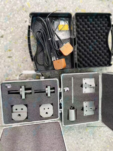
| 10.1 determination of accessible parts of lampholders E5, E10, E14 and E27 (figure 16) | standard test finger (test probe B) Anti-accidental contact gauges (7006-31, 7006-22A, 7006-24) |
| 10.2 determination of accessible parts of enlosed and independent lampholders | standard test finger (test probe B with 10N force) electrical indicator |
| 10.3 Torque test (figure 13, figure 14, figure 15) | Test cap A and Test cap B for lampholders E14 (figure 13) Test cap for lampholders E27 (figure 14) Test cap for lampholders E40 (figure 15) |
| Clause 13 Construction | |
| Clause 13.6 flexible cord | Cord Anchorage Pull Force and Torque Tester |
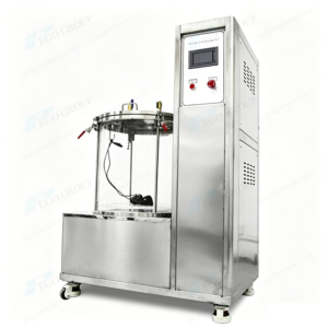
| 14.3 Switches in lampholder | Switch endurance and breaking capacity testing machine |
| Clause 15 Moisture resistance, insulation resistance and electric strength | |
| 15.1 verify the enclosure of drip-proof lampholders against to water | IPX1/2 drip box test chamber |
| 15.3 lampholders shall be proof against humid condition | temperature and humidity chamber |
| 15.4 insulation resistance and electric strength test (figure 11) | insulation resistance tester test Caps E10, E14, E27, E40 (figure 11) withstand voltage tester |
| Clause 16 Mechanical strength | |
| 16.2 mechanical strength of the outer shell, the screw shell and dome (Figure 13, figure 14, figure 15) | Test cap A and Test cap B for lampholders E14 (figure 13) Test cap for lampholders E27 (figure 14) Test cap for lampholders E40 (figure 15) |
| 16.5 strength of the connection between dome and threaded entry (figure 12) | bending apparatus |
| 16.6 mechanical strength of the outer shell and screw shell of metal lampholders (figure 7) | Low energy pendulum hammer impact test apparatus Tumbling barrel |
| 16.7 mechanical strength of external metal parts of metal lampholders (figure 9) | Pressure Apparatus for Metal Lampholders E14, E27 and E40 |
| Clause 18 Creepage distances and clearances | Creepage distance caliper |
| Clause 19 Normal operation (figure 4, figure 5, Figure 13, figure 14, figure 15) | normal operation test apparatus test caps E14, E27, E40 (figure 4) Test cap A and Test cap B for lampholders E14 (figure 13) Test cap for lampholders E27 (figure 14) Test cap for lampholders E40 (figure 15) |
| Clause 20 General resistance to heat | |
| 20.2: For E27 lampholders | Gauge I for checking side contact resiliency in lampholders E27 (7006-22C) Gauge II for checking side contact resiliency in lampholders E27 (7006-22D) |
| For E14 lamphoders | Test cap A and Test cap B for lampholders E14 (figure 13) Heating cabinet |
| 20.3 contact and all other current-carrying parts | test Caps E10, E14, E27, E40 (figure 11) Test cap A and Test cap B for lampholders E14 (figure 13) Test cap for lampholders E27 (figure 14) Test cap for lampholders E40 (figure 15) Go gauge for lampholders E27 (7006-25A) Go gauge for screw threads of lampholders E10, E14, E40 (7006-25) |
| Clause 21 resistance to heat, fire and tracking | |
| 21.1 externail parts of lampholder shall resistance to heat (figure 10) | Ball pressure test apparatus heating cabinet |
| 21.3 external parts of insulating material shall subject to the glow wire test | Glow wire tester |
| 21.4 Parts of insulating material retaining live parts or ELV lamps in position are subjected to needle-flame test | needle-flame tester |
| 21.5 For drip-proof lampholders, insluating parts retaining live parts or ELV parts in position shall be resistance to tracking index test | tracking index tester |
| Figures | |
| Figure 2a – gauges for metric thread for nipples | go and not go gauges for screws and nuts |
| Figure 2b – gauges for ISO standard pipe thread for nipples | |
| Figure 3 – gauge for holes for backplate lampholder screws | Customize |
| Figure 4 – normal operation test apparatus | Normal operation test apparatus |
| Figure 5 – Test Caps for test of clause 18 | Test caps E14, E27, E40 |
| Figure 6 – torque apparatus | Torque apparatus |
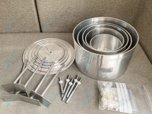
| Figure 7 – tumbling barrel | tumbling barrel |
| Figure 8 – impact test apparatus | Low energy pendulum hammer impact test apparatus |
| Figure 9 – pressure apparatus | Pressure Apparatus for Metal Lampholders E14, E27 and E40 |
| Figure 10 – ball pressure test apparatus | Ball pressure test apparatus |
| Figure 11 – Test cap for the tests of clauses 15.4 and 20.3 | Test caps E10, E14, E27, E40 |
| Figure 12 – bending apparatus | Bending apparatus |
| Figure 13 – test cap A and test cap B for lampholders E14 | Test cap A and Test cap B for lampholders E14 |
| Figure 14 – test cap for lampholders E27 | Test cap for lampholders E27 |
| Figure 15 – test cap for lampholders E40 | Test cap for lampholders E40 |
| Figure 16 – Standard test finger | Test probe B |